


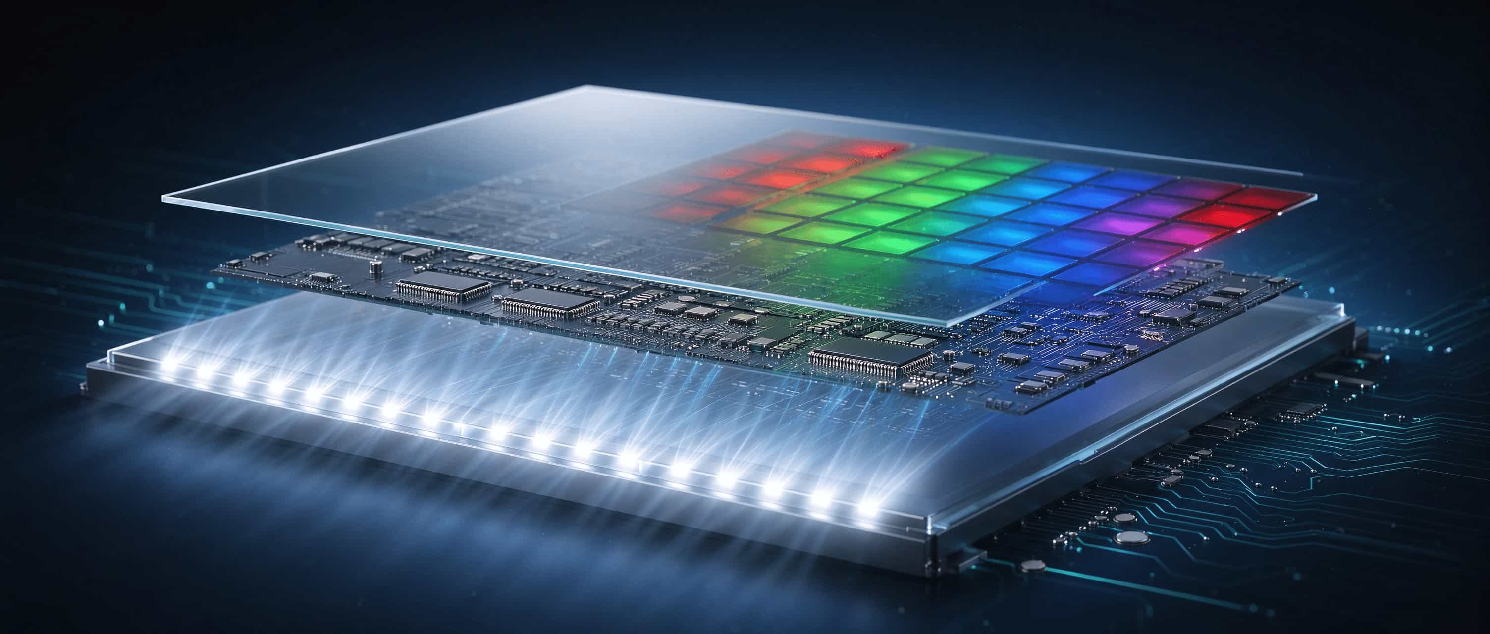
Let me ask you first: Do you really think the light emitted by the LCD screen you stare at for 8 hours a day is natural? No.
In the morning, I check the weather on my phone, during the day, I use my computer to handle work, and in the evening, I read books or binge-watch TV shows on my tablet. Many people spend 8 hours a day staring at screens, and it might even be more.
But you may not know that the LCD you are staring at does not emit light itself. What really shines is the LED backlight behind it. The LCD's job is to control whether the light "passes through" or not.
This system is not mysterious; it's simply a voltage command system. Remember this:
TFT is responsible for sampling, capacitors for maintaining, liquid crystals for translating voltage into light, and RGB for translating light into colors.
Whether you are a purchaser or hardware engineer from an OEM, or a project leader taking over display selection, understanding this chain will make it easier for you to read the specification book without getting confused. When selecting displays for procurement, it will also be easier for you to ask the right questions.
Why can liquid crystal be used in displays.jpg
1. What is liquid crystal? It is neither a liquid nor a crystal
Ordinary liquids have disordered molecules and can flow. Crystals have orderly and regular molecules.
Liquid crystal is sandwiched in the middle: it can flow like a liquid, yet its molecules maintain a certain order. When temperature or pressure changes, its arrangement may also transform. In display technology, people often use an electric field to control it.
Liquid crystal is not a single substance, but a class of substances. There are three common types:
Nematic: The long axes of molecules are oriented in roughly the same direction, like a school of fish swimming forward as a whole. It is sensitive to electric fields and easy to control, making it the core material of mainstream LCDs.
Layered: The molecules are also layered, like a stack of paper. They have higher viscosity and usually slower response, commonly seen in special optical or display scenarios.
Cholesteric: The molecules are arranged in a spiral pattern, capable of reflecting specific wavelengths of light, resulting in structural color. It can be observed in temperature-sensitive materials, color displays, and polarizers.
In displays, nematic type is the mainstream. Remember this:
LCD is not a luminescent material, but a gate for light.
6e56a0cb-798c-41d6-ae22-e090c132dcbd-tuya.jpg
II. How does liquid crystal control light? It's by opening the gate to let light out
LCD pixel, in layman's terms, is two polarizers sandwiching a layer of liquid crystal.
Taking the commonly used normally white TN mode as an example, when no voltage is applied, the liquid crystal molecules twist 90 degrees from top to bottom in a spiral manner. When polarized light passes through, its direction is rotated 90 degrees, aligning perfectly with the upper polarizer. The light passes through, and the pixel becomes bright.
When a voltage is applied, the electric field pulls the liquid crystal molecules upright, causing the helices to unwind. The direction of the polarized light no longer changes and is blocked by the upper polarizer, resulting in a dark pixel.
The voltage is neither too high nor too low, the tilt angle of the molecules changes continuously, and the light transmittance also changes continuously. This results in grayscale.
TN, IPS, and VA differ in their initial molecular arrangement and electric field direction, but share the same link:
Voltage change → molecular rotation → polarization state change → transmittance change.
In a nutshell: The light output is proportional to the voltage supplied.
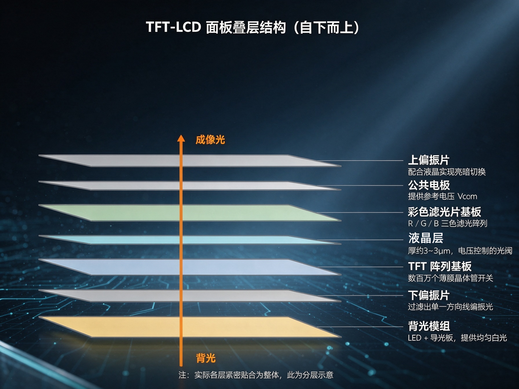
III. A screen is a seven-layer "sandwich"
Note from bottom to top:
26d49acf-6a82-4966-b4db-5170e950f7ed.jpg
Backlight module: LED plus light guide plate, providing uniform white light. Liquid crystal does not emit light by itself, and relies entirely on it for illumination.
Lower polarizer: Organizes the chaotic backlight into linearly polarized light.
TFT array substrate: Millions of thin film transistors are fabricated on the glass, with each transistor corresponding to a subpixel.
Liquid crystal layer: Only 3~5 micrometers thick, it plays a pivotal role in controlling light.
Color filter substrate: Red, green, and blue filters, each corresponding to a sub-pixel.
Common electrode ITO: Provides a unified reference voltage Vcom.
Upper polarizer: In conjunction with the lower polarizer, it determines whether light passes through or not.
In IPS, FFS, and other lateral electric field modes, the common electrode is usually situated on one side of the TFT array substrate, with slightly different layer sequences, but the logic of "who controls the light" remains unchanged.
Remember: The screen is a combination of seven layers, not a single layer of magic.
Fourth, how to remember the voltage of a pixel?
With millions of pixels, it is impossible to connect each one with a dedicated wire. The solution for LCD is to equip each sub-pixel with a small switch and add two capacitors, forming a 1T1C structure.
34dabac1-2c03-489a-8e02-1cf289101cd5.jpg
TFT is a switch transistor. Its gate is connected to the scanning line Gate, its source is connected to the data line Data, and its drain is connected to the pixel electrode. When the Gate is given a high voltage, it is turned on for writing; when given a low voltage, it is turned off for maintaining.
The liquid crystal capacitor Clc, commonly found in medium-sized panels, has a capacitance of approximately 0.1~0.5pF. It serves as both an actuator for driving liquid crystals and a small container for storing charges.
The storage capacitor Cst, typically ranging from 1 to 5 pF, is usually several times the size of Clc. It acts as a "large reservoir" that stores charges, ensuring that the pixel voltage remains almost constant within a frame time (approximately 16.7 ms at 60 Hz), thus preventing image flickering.
To illustrate, let's compare TFT to a water intake valve and Cst to a large water tower on the roof. If the water tower is large enough and the valve is only opened for a brief moment each day, the home will enjoy stable water pressure throughout the day.
There are three steps to drive:
[Sensitive word] step, Gate Driver selects row by row, with VGH typically at +15~+30V. The TFT in this row is simultaneously turned on, while other rows are turned off with VGL typically at -5~-10V.
In the second step, the Source Driver sends the grayscale voltage of each pixel in the row to the data line within a few microseconds, charging Clc and Cst.
Step 3: After the pulse ends, the TFT is turned off, and the pixel is maintained by the capacitor until the next refresh.
The refresh rate is defined as the frequency at which the "gating → writing → holding" process is repeated, ranging from 60 to 144 times per second. The TFT is responsible for sampling, while the capacitor is responsible for holding.
5. How are grayscale and color achieved?
The 8bit panel has a total of 256 levels of grayscale, ranging from 0 to 255, corresponding to different voltage levels. The Source Driver utilizes a Gamma reference voltage divider circuit to translate digital codes into analog voltages.
The Gamma correction on the digital side is completed by the TCON. With the cooperation of both sides, the grayscale is accurate.
Liquid crystal materials will deteriorate if exposed to a direct current electric field for a long time. Therefore, polarity reversal is performed in actual driving, allowing the voltage to alternate between positive and negative values with a mean value of zero.
Colors are blended spatially. Each pixel consists of three sub-pixels: R, G, and B, each independently controlling the grayscale. With 8-bit depth, 256×256×256 ≈ 16.7 million colors. The human eye cannot distinguish three closely adjacent small color blocks, so the brain automatically averages them into one color.
The colors you see are mixed by your brain.
Behind the scenes, there are three brothers: TCON is the conductor, responsible for receiving video signals, generating timing, and performing digital Gamma; Gate Driver decides when to write to which line; Source Driver determines how deeply to write to each pixel. With the collaboration of the three, millions of light valves can dance in sync.
Next time when I look at the specification, VGH, Vcom, STV, and CKH will no longer seem like hieroglyphics. They are just old friends on this link.
When buying or selecting a screen, and communicating with suppliers, don't just focus on the size of the parameters. First, check whether the link is compatible, and then see if the parameters are sufficient.
Remember: The screen doesn't rely on mysticism, it relies on the voltage to clock in on time.
This piece of advice is worth saving. Also share it with the friend who spends every day researching screen parameters, so we can both avoid detours together.
#LCD #Monitor #TFT-LCD #LCD Screen #Parameters #Display Module #LCD Display Module